Veronte products
This section explains how integrate Autopilot 1x with Veronte products.
CEX connection
When communication is established between the PC and the CEX using the Veronte Autopilot 1x as a tunnel, the connection between the CEX and Autopilot 1x is via CAN.
The pin connection between the two devices should be like this:
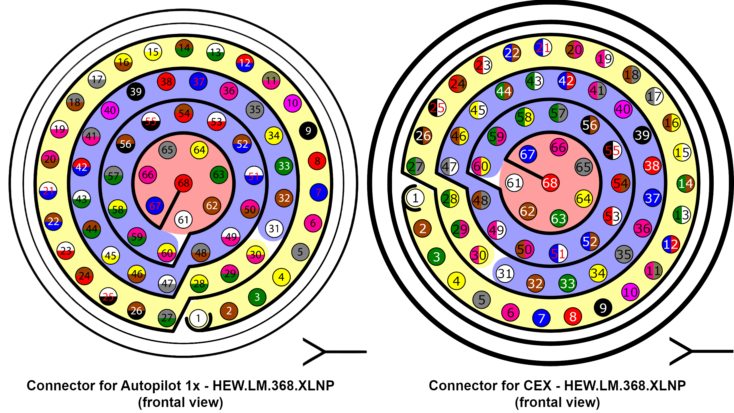
| Autopilot 1x Connector | CEX Connector | ||||
|---|---|---|---|---|---|
| PIN | Signal | Color Code | PIN | Signal | Color Code |
| 25 | CANA_P | White-Black | 5 | CAN (A) P | Gray |
| 26 | CANA_N | Brown-Black | 6 | CAN (A) N | Pink |
| 28 | CANB_P | Yellow-Green | 8 | CAN (B) P | Red |
| 29 | CANB_N | Pink-Green | 9 | CAN (B) N | Black |
| 30 | GND | Yellow-Pink | 7 | CAN GND | Blue |
Note
If only CAN A or CAN B has been configured in the software for communications, only the corresponding pins must be connected.
For more information on CAN connection, please visit CAN - Wiring connection section of this manual.
Warning
Remember!! In Autopilot 1x, all GND pins are common. Note that pin 54 is not a common GND pin.
Important
Integration is also possible by connecting CAN A of the Autopilot 1x to CAN B of the CEX and vice versa, i.e. it does not necessarily have to be CAN A-CAN A or CAN B-CAN B.
However, any connections made must be consistent with the configuration made at software level in 1x PDI Builder and CEX PDI Builder.
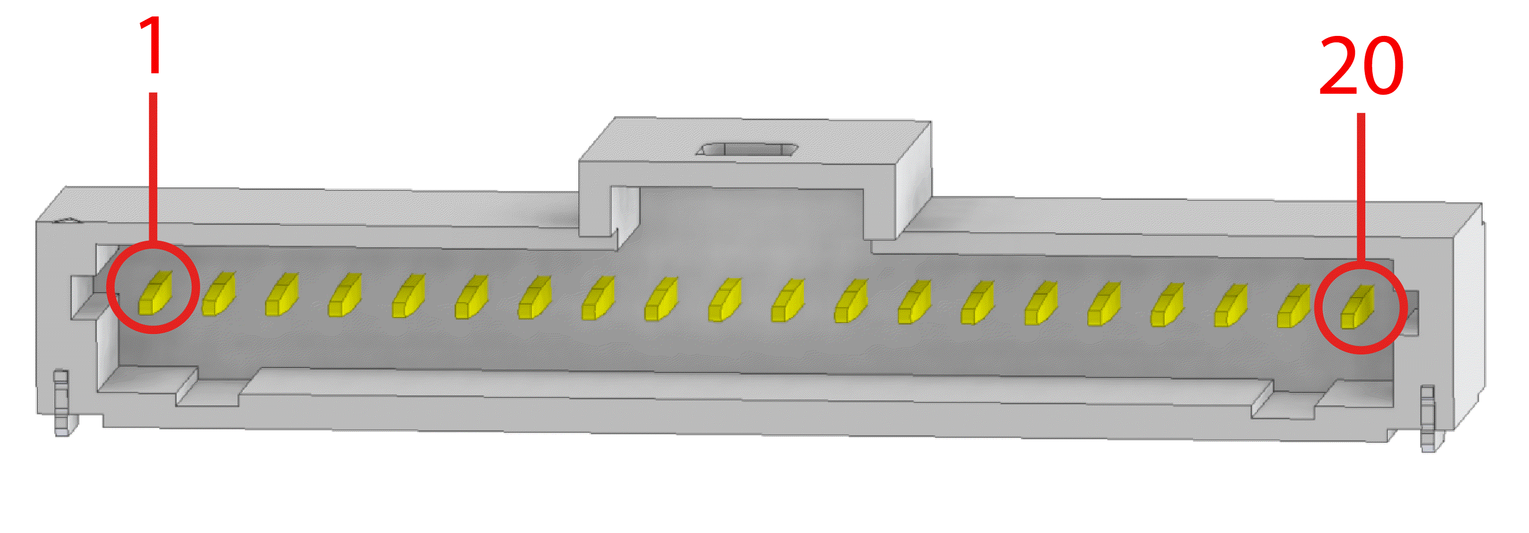
MC01 connection
For proper operation via CAN, the connection between MC01 and Autopilot 1x pins should be like this:
| Autopilot 1x harness | MC01 connector | ||||
|---|---|---|---|---|---|
| PIN | Signal | Color code | PIN | Signal | Color code |
| 25 | CANA_P | White-Black | 9 | CAN (P) | White |
| 28 | CANB_P | Yellow-Green | |||
| 26 | CANA_N | Brown-Black | 8 | CAN (N) | Gray |
| 29 | CANB_N | Pink-Green | |||
| 30 | GND | Yellow-Pink | 10 | GND | Black |
Note
CAN A and CAN B buses are equivalent and can be used interchangeably for the integration of this device.
For more information on CAN connection, please visit CAN - Wiring connection section of this manual.
Warning
Remember!! In Autopilot 1x, all GND pins are common. Note that pin 54 is not a common GND pin.
Once MC01 has been properly wired with the Autopilot 1x, users can proceed to the software integration detailed in the MC01 - Integration examples section of the 1x PDI Builder user manual.
MC24 connection
For proper operation via CAN, the connection between MC24 and Autopilot 1x pins should be like this:
| Autopilot 1x harness | MC24 connector | |||
|---|---|---|---|---|
| PIN | Signal | Color code | PIN | Signal |
| 25 | CANA_P | White-Black | 5 | CANA_P |
| 26 | CANA_N | Brown-Black | 6 | CANA_N |
| 28 | CANB_P | Yellow-Green | 18 | CANB_P |
| 29 | CANB_N | Pink-Green | 7 | CANB_N |
| 30 | GND | Yellow-Pink | 24 | CAN_GND |
Note
If only CAN A or CAN B has been configured in the software for communications, only the corresponding pins must be connected.
For more information on CAN connection, please visit CAN - Wiring connection section of this manual.
Warning
Remember!! In Autopilot 1x, all GND pins are common. Note that pin 54 is not a common GND pin.
Important
Integration is also possible by connecting CAN A of the Autopilot 1x to CAN B of the MC24 and vice versa, i.e. it does not necessarily have to be CAN A-CAN A or CAN B-CAN B.
However, any connections made must be consistent with the configuration made at software level. For this, refer to the MC110/MC24 - Integration examples section of the 1x PDI Builder user manual.
MC110 connection
For proper operation via CAN, the connection between MC110 hardware version 1.2 and Autopilot 1x pins should be like this:
| Autopilot 1x harness | MC110 harness | |||
|---|---|---|---|---|
| PIN | Signal | Color code | PIN | Signal |
| 25 | CANA_P | White-Black | 5 | CANA_P |
| 26 | CANA_N | Brown-Black | 6 | CANA_N |
| 28 | CANB_P | Yellow-Green | 18 | CANB_P |
| 29 | CANB_N | Pink-Green | 7 | CANB_N |
| 30 | GND | Yellow-Pink | 24 | CAN_GND |
Note
If only CAN A or CAN B has been configured in the software for communications, only the corresponding pins must be connected.
For more information on CAN connection, please visit CAN - Wiring connection section of this manual.
Warning
Remember!! In Autopilot 1x, all GND pins are common. Note that pin 54 is not a common GND pin. [!IMPORTANT] Integration is also possible by connecting CAN A of the Autopilot 1x to CAN B of the MC110 and vice versa, i.e. it does not necessarily have to be CAN A-CAN A or CAN B-CAN B.
However, any connections made must be consistent with the configuration made at software level. For this, refer to the MC110/MC24 - Integration examples section of the 1x PDI Builder user manual.
MEX connection
When communication is established between the PC and the MEX using the Veronte Autopilot 1x as a tunnel, the connection between the MEX and Autopilot 1x is via CAN.
The pin connection between the two devices should be like this:

| Autopilot 1x harness | MEX connector | |||
|---|---|---|---|---|
| PIN | Signal | Color code | PIN | Signal |
| 25 | CANA_P | White-Black | 22 | CAN A (P) |
| 26 | CANA_N | Brown-Black | 23 | CAN A (N) |
| 28 | CANB_P | Yellow-Green | 20 | CAN B (P) |
| 29 | CANB_N | Pink-Green | 21 | CAN B (N) |
| 30 | GND | Yellow-Pink | 24 | CAN GND |
Note
If only CAN A or CAN B has been configured in the software for communications, only the corresponding pins must be connected.
For more information on CAN connection, please visit CAN - Wiring connection section of this manual.
Warning
Remember!! In Autopilot 1x, all GND pins are common. Note that pin 54 is not a common GND pin.
Important
Integration is also possible by connecting CAN A of the Autopilot 1x to CAN B of the MEX and vice versa, i.e. it does not necessarily have to be CAN A-CAN A or CAN B-CAN B.
However, any connections made must be consistent with the configuration made at software level in 1x PDI Builder and MEX PDI Builder.
© 2025 Embention. All rights reserved.